| Field | Contents |
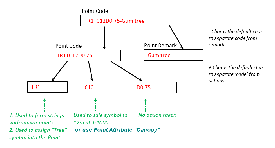
| Cnn | Canopy diameter or spread for a tree (used to scale the size of displayed symbol). Those with nn (Cnn) should be followed by a number (C6.5 = Canopy size = 6.5 meters) Point Attributes: You can use a Point attribute to do the scaling. Add a point Attribute 'Canopy', with a value (scale value). Now setup your config XML file with (scale_attr="Canopy") for a point. |
| Dnn | Diameter of tree trunk, information only - not used by program. |
| Hnn | Height of tree, information only - not used by program |
| Xnnn | Observation is check shot to point nnn. |
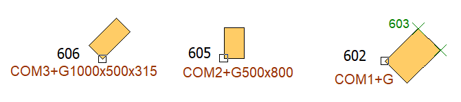
| G | Size and rotate symbol by next 2 shots. This shot and next 2 shots are used to scale and orient the symbol. Usually used for comms pits to scale and orient the symbol to the pit |
| N | Point is to be non contourable |
| R | Point is to have height removed during processing |
| K | Close string to start point. If a function indicator K is on the last point in the string the string will be closed. |
| T | Use next point number for orientation of symbol. Take 2 shots, the first shot st the centre of the symbol with this function indicator, the second shot away from the symbol, the symbol will be oriented towards the second point. |
| O | Orientation of the symbol. Enter the bearing of the symbol. e.g. for 220 degrees symbol enter 'O220' |
| U | Change the point Height by ADDING the supplied value to the height. Enter the height above ground/staff level to be added to the point height. This option can be used to take an observation at ground level, but add the height of the item actually being measured. e.g. for 1.25 metres enter 'U1.25' |
| Z | Change the point Height by SUBTRACTING the supplied value from the height. Enter the depth below ground/staff level to be subtracted from the point height. This option can be used to take an observation at ground level, but subtract the depth of the item actually being measured. e.g. for 0.9 metres enter 'Z0.9' |